Instrument pack bemusement

Moderator: The Midas Forum Staff

Instrument pack bemusement

Postby Maphet » Mon Jun 25, 2012 11:09 pm

Since discovering that my Midas has the wrong instrument pack in (among other oddities) you can imagine my delight when my local breakers finally took delivery of a pre '89 Rover 200. So I cheerfully pull the whole thing out and attempt to stuff it into the gap left by the removal of the Metro instrument pack. It doesn't fit because of the major structural alterations to my dash area, or so I presume. However, I couldn't help noticing that there are a few other significant differences:

Image

As you can see, apart from being longer and differently orientated, the way that the connectors fit is utterly different. The metro ones stick out with two roughly equal sized contact areas, while the 200 ones go in with one small bunch of contacts and one large one. Initially I thought there would be a secondary connector further down the loom as there is in the metro, but having worked through the rover, there clearly isn't.

Just to depress me further, the speedometer drive has the channel for locking it in place on the top on one and the bottom on the other.

I certainly got the impression that the two are interchangable. Reality really seems to disagree, which is a pain as my fascia will only fit the rover one (and it's lovely to look at!

Does anyone have any thoughts, advice or bits that fit!

Cheers,

Matt
Maphet
 
Posts: 50
Joined: Wed Apr 04, 2012 11:48 pm

Re: Instrument pack bemusement

Postby Rich » Tue Jun 26, 2012 12:01 am

It looks like you are going to have to graft the Rover 200 connectors onto your Metro loom. It's a pain in the ass to do but infinitely possible by just working methodically, the same principle I used to fit the digital dash you saw at Stoneleigh.

If the speedo cable will fit enough to take the drive from the cable you could hot glue the two together to stop it falling off. I'm sure some of the guys who have the Rover 200 dash can point you in the direction of the correct cable to use otherwise.
User avatar
Rich
 
Posts: 1283
Joined: Wed Dec 03, 2008 1:27 am
Location: Devon

Re: Instrument pack bemusement

Postby Hans Efde » Tue Jun 26, 2012 7:41 am

Yes mine has the Rover 200 connectors soldered in. Also you need to solder resistors to get a good fuel gauge reading, see a previous post about this (I still have to find out what the resistance of the second resistor is, but will do sowhen I start working on the tank and can disconnect it from the instrument).
The speedocable on mine is just pushed on. Yes there is a chance that it falls off, but it's a sturdy cable with no room to move around. So in practice it stays in place.
There is a build manual addition concerning the Rover instrument. It can be found on the archive website.
User avatar
Hans Efde
 
Posts: 1732
Joined: Sat Dec 06, 2008 10:11 pm
Location: IJlst, Netherlands

Re: Instrument pack bemusement

Postby Maphet » Tue Jun 26, 2012 9:06 am

Thanks Rich and Hans, I was hoping that it would be simple, but of course, what is? Now I have to go and rescue the damn thing and remove the loom...

I really have to write up some of the stuff I have done to her: mostly tales of how much rust you can get in a rustproof car combined with a litany of 'money saving' bodges that I have had to unbodge, potentially lethal neglect and more rust...

For example:

Image

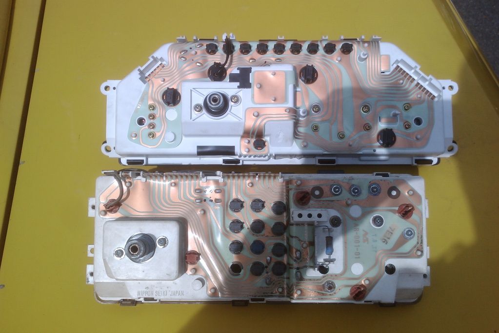
I enjoy wreck diving and, frankly, parts like this look like they came from this Beaufighter

Image

rather than the cabin of a Midas

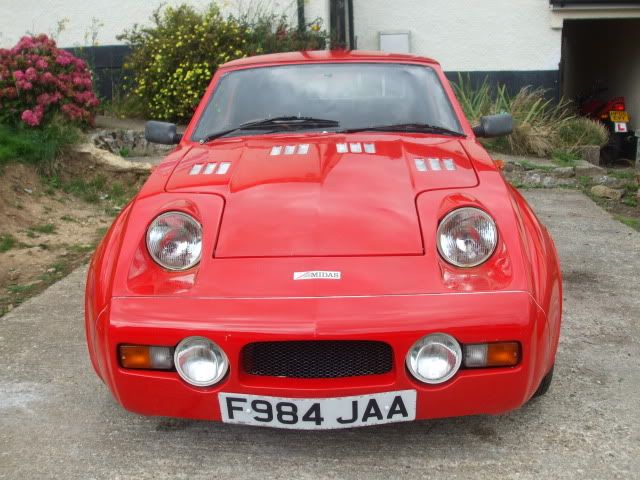
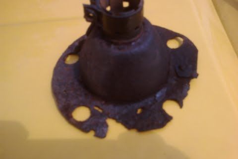
The bottom line is that the car that it becomes increasingly clearly miraculously managed to not only drive to Stoneleigh but enjoy immensely was hanging together: for example: the 'rubber' disk under the steering column was badly torn and generally had the consistency of stringy marshmallow. Fortunately, this rather effectively camouflaged the fact that the pinch bolt underneath was chillingly loose. All of this I was utterly oblivious to, which is hardly embarrassing at all. Any lack of response to deflection of the wheel I was blaming on the uneven hydrogas setup...

As for the carburettor, I'm just really lucky that I have Southern Carburettors on my doorstep and some very patient and extremely knowledgeable people who have negotiated me through the complex ways an SU can keep on working tolerably while sporting the needle from a one litre HLE!

After a rebuild, in which I discovered that the brass tipped needle valve was not only amusingly worn but that the sprung tail had literally drilled a neat hole through the point where it came into contact with the float, that the two grommets in the enrichment circuit were not really either round or rubbery any more while the gasket was neatly folded in half, I thought all would be well.

She ran horribly rich on the standard BDL jet so I tried the one from the HLE again and she ran like a rusty bicycle. After a lot of messing around she's running nicely across the board on a BCC. Quite why this is so on a standard carb manifold, standard Midas stainless exhaust and metro cast exhaust manifold I don't know, but that give me the right air to petrol ratio across the board (well, a tiny bit rich at Idle) and I've replaced or checked everything else so that looks to be the permanent solution.

I hope that's interesting,

Cheers chaps.
Maphet
 
Posts: 50
Joined: Wed Apr 04, 2012 11:48 pm

Re: Instrument pack bemusement

Postby Hans Efde » Tue Jun 26, 2012 9:21 am

That's the reason why I am going to install fuel injection. Seems complicated at first, but the system has very few parts and when it's working it should be a walk in the park setting it up. I am so fed up with SU carburettors.
User avatar
Hans Efde
 
Posts: 1732
Joined: Sat Dec 06, 2008 10:11 pm
Location: IJlst, Netherlands


Return to Mk 3 Convertible

Who is online

Users browsing this forum: No registered users and 2 guests